Features
- Background
- Color coding of velocity and additional data
- Arrow plot
- Velocity dependent size or normalized size
- Color coding
- Streamlines
- Evenly spaced or manually placement
- Euler or Runge-Kutta integration
- Tapering, Glyph mapping, Texture generation
- Support of rectilinear grids
User interface
Transfer functions
For each channel as well as for the velocity its own transfer function. They can be edited by clicking on the button "Define colors".
View
Zooming of the camera can be done either with the mouse scroll or with the right mouse button. Translating the scene can be done with middle mouse button. The button "Reset view" resets the camera settings to the default values.
Background
The values of each channel or the velocity can be displayed via color coding. The colors are changed with the button "Define colors". If the transfer function is disabled the lowest value of the channel will be mapped to black and the highest to white. The display of the background can be disabled.

Arrows
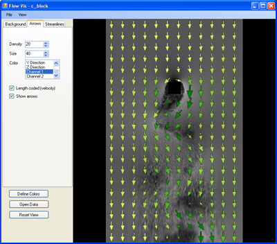
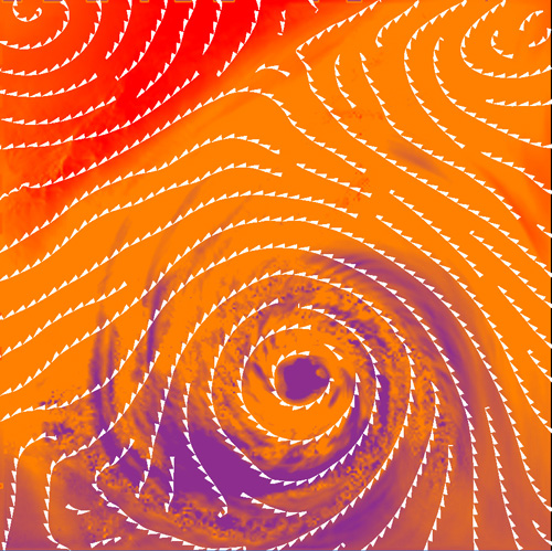
Arrows are regularly distributed over the flow field. They are oriented in the direction of the flow at their position. The parameter "Density" sets the number of arrows along the longer side of the flow field. The size of the arrows can be adjusted with the parameter "Size". The arrows can be displayed equally sized or their size can be modulated with the velocity of the flow. For color coding the same transfer functions as for the background are used.

Streamlines
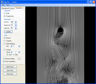
Streamlines show a particle path in a steady flow. Integration can be done either with Euler or with sedond-order Runge-Kutta. The step size is defined with the parameter "dt" which is defined as 1/x of the longest side of the flow field.The placement of the streamlines can be done manually with the left mouse button if "Manual seeding" is enabled. The existing streamlines can be deleted with the button "Clear". Changing the integration mode or the step size only affects newly created streamlines.
If manually seeding is disabled the streamlines are placed evenly spaced. The distance of new streamlines to the existing ones is defined with the parameter "dsep". The parameter "dtest" sets the distance for stopping a streamline if it gets too near to other streamlines. It is given in percent of the value for "dsep".
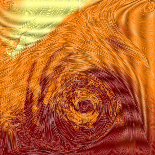
The style of the streamlines can be altered with different methods. Tapering changes the width of a streamline according to its distance to neighboured streamlines (only for evenly spaced streamlines). Glyph mapping uses the streamline as skeleton to map directional glyphs on it. Texture generation is useful for very dense streamlines. A periodic function is used to show the direction of the flow.

Results


